PSpice A/D Circuit Simulator
Advanced simulation for analog and mixed-signal environments
Cadence® PSpice® A/D is a full-featured analog simulator with support for digital elements to help solve virtually any design challenge—from high-frequency systems to low-power IC designs. The powerful simulation engine integrates easily with Cadence PCB schematic entry solutions, improving time to market and keeping operating costs in check. An interactive, easy-to-use graphical user interface provides complete control over the design process. Availability of resources such as models from many vendors, built-in mathematical functions, and behavioral modeling techniques make for an efficient design process.
BENEFITS:
- Improves simulation time, reliability, and convergence on larger designs
- Improves speed without loss of accuracy via integrated analog and event-driven digital simulations
- Explores circuit behavior using basic DC, AC, noise, and transient analyses
- Offers library selection of more than 34,000 analog and mixed-signal models
- Allows for automatic identification of analog and digital signals and applies A-to-D and D-to-A interfaces
- Explores design relationships with “what if” scenarios before committing to hardware
- Identifies and simulates functional blocks of complex circuitry using mathematical expressions, functions, and behavioral devices
FEATURES
Design Entry and Editing
PSpice A/D integrates seamlessly with the Cadence front-to-back PCB design flow, making it possible to have a single, unified design environment for both simulation and PCB design. Select from a library of more than 34,000 symbols and models for simulation to design with Cadence PCB schematic design entry technology.
Stimulus Creation
Access built-in functions that can be described parametrically or draw piece-wise linear (PWL) signals freehand with the mouse to create any shape stimulus. Create digital stimuli for signals, clocks, and buses; click-and-drag to introduce and move transitions.
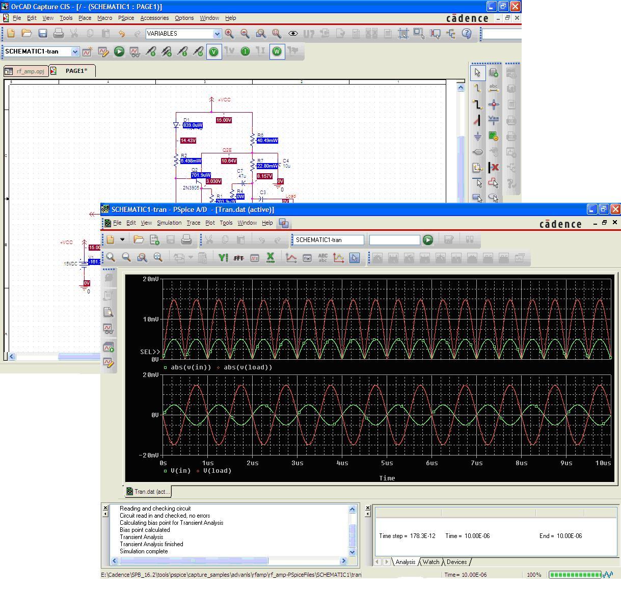
Circuit Simulation
Users can easily set up and run simulations, and then cross-probe simulation results from Probe, an industry-standard waveform viewer. Support for multiple simulation profiles enables users to recall and run different simulations on the same schematic.
Mixed Analog/Digital Simulation
Integrated analog and event-driven digital simulations improve speed without loss of accuracy. A single graphical waveform analyzer displays mixed analog and digital simulation results on the same time axis.
Graphical Results and Data Display
Probe Windows allows users to choose from an expanded set of mathematical functions to apply to simulation output variables. Designers can create plot window templates and use them to easily make complex measurements by simply placing markers directly on the desired pins, nets, and parts in the schematic.
Models
Included are a large variety of accurate internal models—which typically include temperature effects— that add flexibility to simulations. Models are available with R, L, C, and bipolar transistors plus: built-in IGBTs; Seven MOSFET models; five GaAsFET models; nonlinear magnetic models; transmission line models; digital primitives; and two battery models.
Model Library
Users can select from more than 25,000 analog and mixed-signal models of devices made in North America, Japan, and Europe. Also included are more than 4,500 parameterized models for BJTs, JFETs, MOSFETs, IGBTs, SCRs, magnetic cores and toroids, power diodes and bridges, operational amplifiers, optocouplers, regulators, PWM controllers, multipliers, timers, and sample-and-holds.
Behavioral Modeling
Functional blocks are described using mathematical expressions and functions, which allows designers to leverage a full set of mathematical operators, nonlinear functions, and filters. Circuit behavior can be defined in the time or frequency domain, by formula (including Laplace transforms), or by look-up tables.
Magnetic Parts Editor
The Magnetic Parts Editor helps designers overcome issues involved in manually designing transformers. Users can design magnetic transformers and DC inductors, and generate simulation models for trans-formers and inductors.
Checkpoint Restart
This feature allows designer to store simulation states at various time-points and then restart simulations from any of the simulation states, which saves time. The designer can modify simulation settings and design parameters before starting a simulation from a pre-recorded time-state.
Auto-Convergence Option
This option makes the simulator automatically change tolerances limits of convergence to make the design converge. Designers can use this option to achieve convergence and then fine-tune simulations by further modifying simulator options.
-------------------------------------------------------------------------------------------------------------------------------------------------------------------------------------------
Click on Data Sheet to download
Click on image for enlarged view